
LC resonance and Q
Resonance of an inductor and a capacitor: a tank in an oscillator or a filter, a series trap, a matching network. The Simple view gives f0, the characteristic impedance, Q and the bandwidth. The Advanced view uses real parts (the inductor’s Q, DCR and self-resonance, the capacitor’s loss and ESL, the board stray), the source and load, the tolerance and temperature, and the stress at resonance. Group Circuit. Search words include lc, resonance, tank, q, bandwidth, characteristic impedance and f0.
The window, the Simple and Advanced views, full screen and the place buttons are in The calculator window.
51.1Simple: f0, Z0 and Q
| Choice | Options | What it does |
|---|---|---|
| Circuit | Series, Parallel tank | Series: the output is taken across R, a band pass that peaks at f0. Parallel tank: fed through R, which sets its Q. |
| Field | Unit | Default | What it does |
|---|---|---|---|
| Inductance | nH, µH, mH | 10 µH | SOLVE. Reads a selected inductor. |
| Capacitance | pF, nF, µF | 100 pF | SOLVE. Reads a selected capacitor. |
| Resonant frequency | Hz, kHz, MHz | 5.033 MHz (solved) | SOLVE, solved when the calculator opens. |
| Resistance | Ω, kΩ | 10 Ω | In series with L and C, or feeding the tank. Reads a selected resistor. |
f0 = 1 / 2π√(LC), Z0 = √(L/C), Q = Z0/R (series) or R/Z0 (tank), BW = f0/Q, and L or C from f0 and the other.
| Result | What it is |
|---|---|
| Resonance f0 | Orange. |
| Characteristic Z0 | |
| Q | |
| Bandwidth (−3 dB) |
"Q is 0.032, below 0.5: the circuit is overdamped and shows no peak." warns when Q is under 0.5. The Response plot is the circuit’s own transfer around f0 with f0 and the −3 dB edges marked.
| Button | What it does |
|---|---|
| Place as circuit | V1 (1 V at f0), L1, C1 and R1 as series or tank, IN and OUT probed. |
| Place and run AC analysis | The same and an AC sweep at 200 points per decade. Resonance gain at f0 within ±0.05 dB of 0 dB and Resonance phase at f0 within ±1°. |
| Apply to selected parts | With an inductor and a capacitor selected: l and c. |
- Open LC resonance and Q (type
lc): series, 10 µH, 100 pF, 10 Ω. - Press Place and run AC analysis.
You should seef0 5.03 MHz, Z0 316 Ω, Q 31.6, bandwidth 159 kHz. The AC run reads 0 dB and 0° at f0 and both pass.
51.2Advanced: real parts
| Choice | Options | What it does |
|---|---|---|
| Circuit | Parallel tank, Series | Loads that circuit’s source, load and band: series 50 Ω and 50 Ω for 1.5 MHz, parallel 10 kΩ and 10 kΩ for 300 kHz. |
| Solve | f0 from L, C, C for f0, L for f0 | C or L is then SOLVED, worked out with the strays subtracted and rounded to E24 (C) or E12 (L). |
| Tab | Its dot | Cards |
|---|---|---|
| Design | Amber with a warning. | Result, Response with part tolerances, Parts. |
| Q and bandwidth | The insertion loss, bandwidth and spread checks. | Q budget, f0 vs temperature, Checks. |
| Parts and stress | The SRF, voltage, current and dielectric checks. | Impedance of the tank, Stress at resonance, Formulas. |
| Verify in simulation | None. | Calculator vs simulation. |
| Field | Unit | Default | What it does |
|---|---|---|---|
| L, C, f0, Board stray | µH, pF, MHz, pF | 10, 100, 5, 2 | Group Resonator. |
| Tolerance, Q at f0, DCR, SRF, Tempco, I rating | ±%, , Ω, MHz, ppm, A | 5, 50, 0.3, 60, 100, 0.5 | Group Inductor (datasheet). |
| Tolerance, DF (tan δ), ESL, Rated, Dielectric | ±%, %, nH, V | 2, 0.1, 0.6, 50, C0G | Group Capacitor. Film and X7R too. |
| Source R, Load R, Drive, BW target | Ω (kΩ for a tank), V pk, kHz | 50, 50, 1, 1500 | Group Source, load and range. |
| T min, T max | °C | −20, 70 |
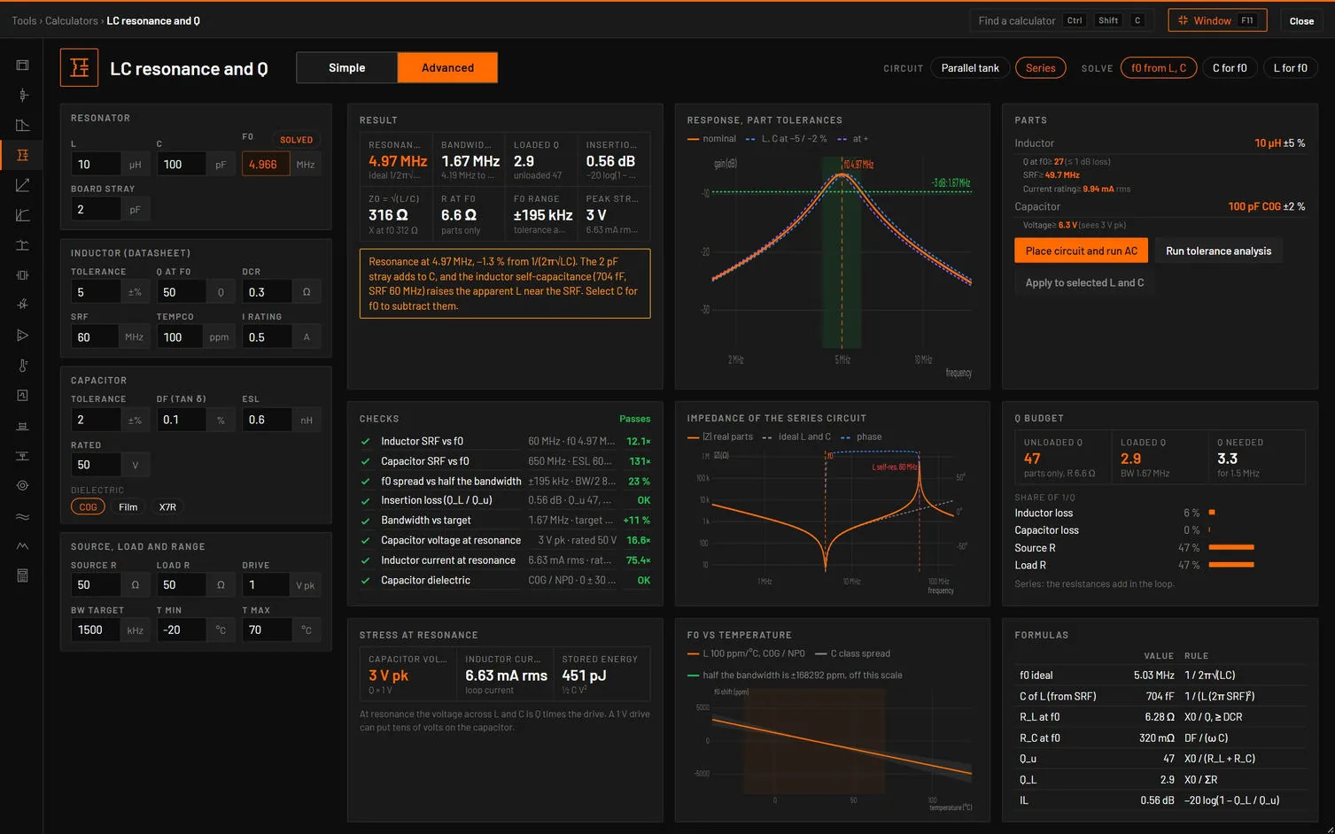
How it works it out. The inductor is (Rac + jωL) in parallel with its self-capacitance Cp = 1 / (L (2π SRF)²), with Rac = X / Q at f0, growing as √f and never below the DCR. The capacitor is DF/(ωC) + jωESL + 1/(jωC). The stray sits across the tank. The resonance of the real tank is the peak (tank) or minimum (series) of |Z|, found numerically, and so are the −3 dB edges. Unloaded Q = X0 / (RL + RC), Rp = Q X0, loaded Q from Rp, the source and the load, insertion loss −20 log(1 − QL/Qu) (Zverev).
| Result | What it is |
|---|---|
| Resonance | Of the real parts, and the ideal 1/2π√LC. |
| Bandwidth | With its edges. |
| Loaded Q | And the unloaded Q. |
| Insertion loss | −20 log(1 − QL/Qu). |
| Z0 = √(L/C), R or Rp at f0 | |
| f0 range | Over tolerance and temperature. Amber above a quarter of the bandwidth. |
| Peak stress | The capacitor voltage and the current in L. |
The Parts card asks for the inductor’s Q for under 1 dB loss, an SRF of at least 10 × f0, a current rating of 1.5 × the RMS, a C0G capacitor and twice the peak voltage, and a trimmer when the spread is wide. When C or L is solved, a table shows the standard values around it with their f0 and error. Q budget shows each loss’s share of 1/Q (inductor, capacitor, source, load).
| Check | Value and limit | Passes | Marginal | Fails |
|---|---|---|---|---|
| Inductor SRF vs f0 | SRF · f0 | 10 × or more | 3 × or more | Less |
| Capacitor SRF vs f0 | 1/2π√(ESL C) · f0 | 10 × or more | 3 × or more | Less |
| f0 spread vs half the bandwidth | ±spread · BW/2 | Under BW/4 | Under BW/2 | More |
| Insertion loss (Q_L / Q_u) | dB | 1 dB or less | 3 dB or less | More |
| Bandwidth vs target | % | Within ±20 % | Within ±50 % | More |
| Capacitor voltage at resonance | V pk · rated | 2 × margin | 1.2 × margin | Less |
| Inductor current at resonance | I rms · rated | 1.5 × margin | Within it | Over |
| Capacitor dielectric | C0G, film, X7R | C0G or film | X7R: not for tanks |
| Message | When it shows |
|---|---|
| "Resonance at 4.97 MHz, −1.3 % from 1/(2π√LC). The 2 pF stray adds to C, and the inductor self-capacitance (704 fF, SRF 60 MHz) raises the apparent L near the SRF. Select C for f0 to subtract them." | The real f0 is more than 1 % from the ideal. |
| "Tolerance and temperature move f0 by ±…, … % of half the bandwidth. Use ±1 % C0G and a ±2 % inductor, add a ±… trimmer or widen the band." | Spread over a quarter of the band. |
| "Loaded Q … is … % of the unloaded Q …, so … dB is lost in the parts. An inductor with Q ≥ … at f0 brings the loss under 1 dB." | Insertion loss over 1 dB. |
| "Inductor SRF 6 MHz is close to f0, where L and Q differ from the datasheet table. Use a part with SRF ≥ 10 × f0." | SRF under 3 × f0. |
| "Capacitor voltage at resonance is … peak (Q times the drive). Use a … V part." | Over the rating with margin. |
| "The inductor self-capacitance and the stray resonate with L below this frequency. Use a smaller L." | Solving C finds none. |
| "The target is above the inductor self-resonance, so no L value fits. Use a part with a higher SRF." | Solving L finds none. |
| Check | Analysis and measurement | Limit |
|---|---|---|
| Gain at f0 | AC around f0 with the real parts (L1 dcr and srf, C1 esr and esl) | ±0.3 dB |
| Resonance, −3 dB bandwidth | Read from the AC plot | |
| f0 spread | Tolerance analysis: 100 Monte Carlo runs of L and C, gain at the nominal f0 inside the −3 dB band | The yield |
| Button | What it does |
|---|---|
| Place circuit and run AC | V1 at the drive, RS, the tank or series L1 and C1 with their losses (and a separate stray for a tank), RL, and an AC sweep at 200 points per decade. |
| Run tolerance analysis | tol on L and C and a Monte Carlo of 100 AC runs. |
| Apply to selected L and C | Their values. |
| Simple | Advanced |
|---|---|
| Inductance, Capacitance, Resonant frequency | L, C, f0 |
| Circuit | Circuit |
- Open LC resonance and Q, press Advanced: series, inductor Q 50, SRF 60 MHz, C0G, 2 pF stray, 50 Ω source and load.
You should seeThe resonance is at 4.97 MHz, 1.3 % under the ideal 5.03 MHz, and the warning says the stray and the inductor’s self-capacitance pull it. Bandwidth 1.67 MHz (4.19 to 5.87 MHz), loaded Q 2.9 against 47 unloaded, 0.56 dB insertion loss, f0 range ±195 kHz. All eight checks pass. Set Solve to C for f0 at 5 MHz: exact 99.32 pF, E24 100 pF (−0.68 %).
Sources. Textbook second-order resonance (Hayt and Kemmerly), and Zverev, Handbook of Filter Synthesis, for the insertion loss. The tests check f0, the series and tank bandwidths, the pull of the self-capacitance and stray (−1.3 %), the insertion loss, and the placed circuits’ gain and tolerance yield against bspice.