
Heatsink and junction
How hot a power part’s junction gets, and the heatsink, interface or copper it needs. The Simple view is the series ladder of thermal resistances. The Advanced view adds the part’s transient thermal impedance (four Foster stages), pulses, interface materials, PCB copper with vias, natural or forced air, an enclosure, derating and other parts on the same heatsink. Group Parts. Search words include thermal, heatsink, junction, theta, rth, derating and tj.
The window, the Simple and Advanced views, full screen and the place buttons are in The calculator window.
60.1Simple: the thermal ladder
| Field | Unit | Default | What it does |
|---|---|---|---|
| Power dissipated | W | 5 | Reads the selected part, or its mean power while the live view runs. |
| Junction to case θJC | °C/W | 1.5 | From the part’s datasheet. |
| Case to heatsink θCS | °C/W | 0.5 | Paste or pad. Typical 0.2 to 1. |
| Heatsink to ambient θSA | °C/W | 8 (solved) | SOLVE. The heatsink needed for the junction limit. |
| Ambient temperature | °C | 25 | |
| Junction limit | °C | 125 | The datasheet maximum, or a lower design limit. |
Tj = Ta + P (θJC + θCS + θSA), Tc = Ta + P (θCS + θSA), Ts = Ta + P θSA, and the heatsink needed is θSA = (Tjmax − Ta) / P − θJC − θCS. θSA is the only field with SOLVE and it opens solved, so this view shows the heatsink needed for the limit.
| Result | What it is |
|---|---|
| Heatsink needed | The θSA for the junction limit (orange). |
| Junction Tj, Case Tc, Heatsink Ts | |
| Total θ | θJC + θCS + θSA. |
| Power limit | (Tjmax − Ta) / total θ. |
| Message | When it shows |
|---|---|
| "θJC and θCS alone give Tj 175 °C at 50 W. No heatsink holds 125 °C. Lower the power, the ambient or the resistances." | The solved θSA is zero or negative. |
| "Tj is within 15 °C of the limit. Keep margin for hot days and for θ rising with age." | Little margin. |
| "Heatsink above 90 °C, hot enough to burn skin and to heat nearby parts." | Ts over 90 °C. |
| "θCS above 2 °C/W points to a poor interface. Check the pad or paste and the mounting torque." | θCS over 2. |
The drawing Thermal ladder shows Tj, Tc, Ts and Ta with each resistance and its drop (Heat flows left to right: each resistance drops P × θ degrees). Add the result as a note puts a text on the sheet: Thermal: 5 W at 25 °C ambient / Tj 125 °C, Tc 117.5 °C, Ts 115 °C / θJC 1.5 + θCS 0.5 + θSA 18 °C/W.
- Open Heatsink and junction (type
heatsink): 5 W, θJC 1.5, θCS 0.5 °C/W, 25 °C, limit 125 °C.
You should seeHeatsink needed 18 °C/W. Tj 125 °C, Tc 117.5 °C, Ts 115 °C, total θ 20 °C/W, power limit 5 W, and the warning that the heatsink is above 90 °C.
60.2Advanced: heatsink, board and pulses
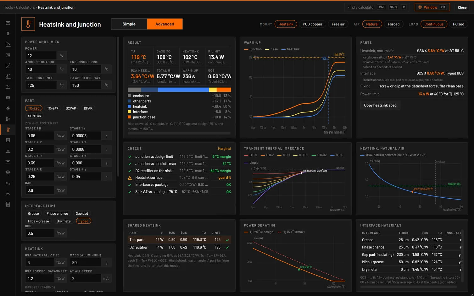
| Choice | Options | What it does |
|---|---|---|
| Mount | Heatsink, PCB copper, Free air | PCB copper changes a TO-220 or TO-247 to D2PAK and lowers a power over 5 W to 2.5 W. Heatsink from a small package picks TO-220. |
| Air | Natural, Forced | |
| Load | Continuous, Pulsed |
| Tab | Its dot | Cards |
|---|---|---|
| Design | The worst check. | Result, Parts, Checks. |
| Pulses | Pulsed: red when the peak Tj is over Tj max, amber over the design limit or with a swing over 40 °C. | Transient thermal impedance, Warm-up or Tj pulse train, Pulse train. |
| Heatsink and board | Red over Tj max, amber over the design limit. | The mount plot, Interface materials or Board changes and Thermal vias, Parts. |
| Derating | Green within the power limit, else red. | Power derating, Checks. |
| Shared heatsink | Heatsink with other parts on: red when one is over its limit, amber within 25 °C of it. | Shared heatsink. |
| Verify in simulation | None. | Calculator vs simulation. |
| Field | Unit | Default | What it does |
|---|---|---|---|
| Power (or Pulse power, Pulse width, Period) | W (W, ms, ms) | 12 (60, 5, 50) | Group Power and limits. Pulsed shows the average and the duty. |
| Ambient outside, Enclosure rise | °C | 40, 10 | The air at the part is outside plus the rise. |
| Tj design limit, Tj absolute max | °C | 125, 150 | |
| Package | TO-220, TO-247, D2PAK, DPAK, SON 5×6 | Group Part. Sets the contact area, θJC and θJA: TO-220 1.1 cm², 0.9, 62 °C/W, TO-247 2.4 cm², 0.45, 40, D2PAK 0.9 cm², 0.9, 62, DPAK 0.36 cm², 1.5, 100, SON 5×6 0.2 cm², 1.2, 125. | |
| Stage 1 to 4 R and τ | °C/W, s | 0.06/30 µs, 0.2/0.6 ms, 0.39/6 ms, 0.25/40 ms | Zth j-c as four Foster stages (the die-attach stack). |
| θJC | °C/W | 0.9 | Editing it scales the four stages to sum to it. |
| Interface | Grease, Phase change, Gap pad, Mica + grease, Dry metal, Typed | Group Interface (TIM), heatsink only. A material gives θCS = t/(kA) + Rc/A from its thickness, k and contact resistance (grease 25 µm, 0.8 W/mK). | |
| θCS | °C/W | 0.5 | Typed interface. |
| θSA natural, ΔT 75 | °C/W | 3.0 | Group Heatsink: the catalogue rating at a 75 °C rise. |
| Mass (aluminium) | g | 80 | For the warm-up time. |
| θSA forced, datasheet, at air speed, Your air speed | °C/W, m/s, m/s | 1.2, 2, 2 | Forced air. |
| Base width, length, thickness, spreading | mm | 50, 60, 4, In θSA | Add spreading adds the base spreading resistance. |
| Copper area top, Lower layers, Thermal vias, Via drill, Plating, Board thickness, Board area | cm², cm², , mm, µm, mm, cm² | 6.45, 6.45, 9, 0.3, 25, 1.6, 50 | PCB copper. Also 1 oz or 2 oz, 1, 2 or 4 layers, vertical or horizontal, bare board ignored or included. |
| θJA (datasheet) | °C/W | 62 | Free air. |
| Other parts, same heatsink | D2 rectifier 4 W on | Up to three rows: name, power, Tj max, θJC, θCS, each with a tick. |
How it works it out. A natural-convection θSA scales as (75/ΔT)0.25, solved together with the rise the total power gives. Forced air scales as 1/√v. The heatsink carries this part and the other ticked parts, and each junction sits P (θJC + θCS) above it. The PCB mount is an annular copper fin (Incropera) with convection and radiation from both faces, lower layers through plated vias and the FR-4, solved together with its temperature. Pulses use the Foster stages plus the interface and mount stages (the heatsink’s τ from its θ and mass): the periodic steady state by superposition, the single pulse as Zth(tp) = Σ R (1 − e−tp/τ), and the datasheet form D·Rth + (1 − D)·Zth(tp).
| Result | What it is |
|---|---|
| Tj (Tj peak when pulsed) | Against the design limit and the maximum. Amber over the design limit, red over the maximum. |
| Case Tc | |
| Heatsink, Board under part, or Inside ambient | Its temperature, with what flows into it. |
| P limit | The continuous power for the design limit. |
| θSA needed, Copper needed, or θJA used | With the catalogue equivalent at ΔT 75 °C, or the air speed, or the 2 oz and 1 oz copper per layer. |
| Total θ | Rise over average power. |
| Warm-up or Swing | The mount’s time constant, or the Tj swing per pulse. |
| θCS or Vias | The interface, or the vias and their θ. |
A stacked bar shows the rise above the outside air: enclosure, other parts, heatsink, interface and junction to case. Parts gives the heatsink to buy (θSA at the working rise and at ΔT 75, a volume range, the air speed needed), the interface, its insulation and the fixing, or the copper, vias and layers for a PCB.
| Check | Value and limit | Passes | Marginal | Fails |
|---|---|---|---|---|
| Junction vs design limit | Tj · limit | Within it | Up to Tj max | Over |
| Junction vs absolute max | Tj · max | 20 °C margin | Within it | Over |
| Temperature swing per pulse | °C | 40 °C or less | 80 °C or less | More |
| Tj, single pulse | Tj · Zth(tp) | Within Tj max | Over | |
| D2 rectifier on the sink | Tj · its max | 25 °C under it | Within it | Over |
| Heatsink surface | Ts | 60 °C or less | Hotter: guard it | |
| Interface vs package | θCS · θJC | θCS ≤ θJC | Up to 2 × θJC | More |
| Sink ΔT vs catalogue 75 °C | ΔT | 40 °C or more | Less: θSA is worse than the catalogue | |
| Board next to the part | Ts · FR-4 105 °C | 105 °C or less | 130 °C or less | More |
| Message | When it shows |
|---|---|
| "Tj 188 °C is above the 150 °C maximum. Use θSA ≤ 0.97 °C/W, a better interface or forced air." | Over the maximum on a heatsink. On a PCB: Board limit … Add copper and vias or use a heatsink. In free air: Add a heatsink. |
| "Tj 24 °C above the 125 °C design limit." | Over the design limit. |
| "θCS … °C/W is above θJC … °C/W. Use grease or phase change on a flat heatsink, or a thinner pad." | The interface dominates. |
| "Heatsink rise 52 °C. Catalogue natural-convection θSA is for ΔT 75 °C, so θSA is 9 % higher here (included)." | A rise under 40 °C... or any rise below 75 °C that changes θSA. |
| "ΔTj … °C per pulse. Repeated swings fatigue the die attach and bond wires. Lower the pulse power or add thermal mass near the die." | A swing over 40 °C. |
| "D2 rectifier: Tj … °C, above its 175 °C limit." | A shared part over its limit. |
Verify in simulation places the thermal network as a circuit (1 A = 1 W, 1 V = 1 °C, 1 Ω = 1 °C/W, 1 F = 1 J/K): a current source of the average power into TJ, each stage as R in parallel with C = τ/R, a source for the ambient. It checks Steady Tj and Heatsink Ts (operating point), Warm-up, Tj at τ (transient) and Zth single pulse at tp. The heatsink θ from the air flow or copper and the peak Tj of a pulse train are calculator only.
| Button | What it does |
|---|---|
| Place thermal network | The network (P_TJ, RTHn, CTHn, P_OTHERS, V_AMB), TJ and TS labelled, an operating point. Measurements Junction temperature V(TJ) and Heatsink temperature (or Board temperature) V(TS), ±0.1 °C. |
| Apply θ | With a diode, LED, transistor, regulator or op-amp selected: rth_jc, rth_ca, tamb and cth on it, so its self-heating gives the same Tj. |
| Simple | Advanced |
|---|---|
| Power dissipated, Ambient temperature, Junction limit | Power, Ambient outside, Tj design limit |
| θJC, θCS, θSA | θJC, typed θCS, θSA natural ΔT 75 |
- Open Heatsink and junction, press Advanced: 12 W, TO-220, natural air, 3 °C/W at ΔT 75, 40 °C plus 10 °C in the box, a 4 W rectifier on the same heatsink.
- Press Place thermal network.
You should seeTj 119.3 °C, Tc 108.5 °C, the heatsink at 102.5 °C with 16 W in 3.28 °C/W (its θ at a 52 °C rise), power limit 13.4 W, θSA needed 3.64 °C/W (3.41 in the catalogue), warm-up 236 s. The rectifier runs at 110.6 °C. Heatsink surface is amber (guard it). V(TJ) reads 119.3 °C and passes.
- Set Mount to PCB copper: 2.5 W, 6.45 cm² of 2 oz on two layers, nine vias.
You should seeTj 148.8 °C with θ board 38.6 °C/W and a power limit of 1.76 W. It needs 13.5 cm² of 2 oz per layer (15.8 cm² of 1 oz). Board next to the part fails at 147 °C against the 105 °C FR-4 limit.
Sources. JEDEC JESD51-1 and TI SPRA953 for the thermal ladder, Incropera for the annular fin, Lee, Song, Au and Moran (1995) for spreading, Abramowitz and Stegun 9.8 for the Bessel functions. Interface and thick-film figures are typical and marked to be replaced by yours. The tests check the ladder, the (ΔT/75)−0.25 scaling, θCS for grease (0.42 °C/W on 1.1 cm²), the Foster stack, and the placed network against bspice.