
Attenuator pads
Resistive pads that lose a set number of decibels while matching the impedance on both sides: to tame a hot signal, isolate a mixer or a cable, or match 75 Ω to 50 Ω. The Simple view gives symmetric Pi and T pads. The Advanced view adds the bridged T and the minimum-loss L pad, unequal ports, the power in each resistor, the tolerance and the package parasitics. Group Circuit. Search words include attenuator, pad, pi pad, t pad, db, matched and 50 ohm.
The window, the Simple and Advanced views, full screen and the place buttons are in The calculator window.
54.1Simple: Pi and T pads
| Choice | Options | What it does |
|---|---|---|
| Pad | Pi pad, T pad | |
| Part values | Exact, Nearest E12, Nearest E24, Nearest E96 | Rounded to the nearest of the series. |
| Field | Unit | Default | What it does |
|---|---|---|---|
| Attenuation | dB | 10 | |
| Impedance | Ω, kΩ | 50 | Source and load. |
With K = 10dB/20: Pi R1 = R3 = Z (K + 1) / (K − 1) to ground and R2 = Z (K² − 1) / 2K in series. T R1 = R3 = Z (K − 1) / (K + 1) in series and R2 = 2ZK / (K² − 1) to ground.
| Result | What it is |
|---|---|
| R1, R3 and R2 | Rounded to the series (orange). |
| Attenuation | What the rounded pad gives between Z and Z. |
| Error | Attenuation given minus asked. |
| Input impedance | Of the rounded pad with Z at the other end. |
A table By series compares Exact, E12, E24 and E96 (values, attenuation, error, input Z). "Enter an attenuation above 0 dB." shows at 0 dB or less.
| Button | What it does |
|---|---|
| Place and run AC analysis | V1 (1 V, 1 kHz), RS = Z, the pad, RL = Z, IN and OUT probed, an AC sweep 10 Hz to 1 MHz. Measurement Pad gain at 1 kHz within ±0.02 dB of −(attenuation + 6.02 dB): the matched source halves the voltage. |
| Place as circuit | The same with no analysis. |
| Apply to selected resistors | With three resistors selected: R1, R2, R3. |
- Open the attenuator pads: Pi, 10 dB, 50 Ω, E24.
- Press Place and run AC analysis.
You should seeR1 = R3 = 100 Ω and R2 = 68 Ω (exact 96.2 Ω and 71.2 Ω). They give 9.63 dB, an error of −0.37 dB, and 50.33 Ω in. OUT reads 15.65 dB below the source and the measurement passes.
54.2Advanced: four pads and their limits
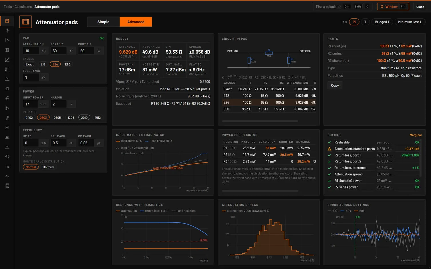
| Choice | Options | What it does |
|---|---|---|
| Pad | Pi, T, Bridged T, Minimum-loss L | The L pad matches two impedances with the least loss: with equal ports it sets 75 Ω and 50 Ω. |
| Tab | Its dot | Cards |
|---|---|---|
| Design | The worst check. | Result, Circuit, Parts, Values by series. |
| Power | Green when every resistor’s need fits its package, else amber. | Power per resistor, Checks. |
| Match and tolerance | Green when the worst return loss of the Monte Carlo is 20 dB or more. | Input match vs load match, Attenuation spread, Values by series, Error across settings. |
| Frequency | Amber when the response drifts below the top frequency. | Response with parasitics. |
| Verify in simulation | None. | Calculator vs simulation. |
When the pad cannot be built only Design shows, with a red dot and the reason.
| Field | Unit | Default | What it does |
|---|---|---|---|
| Attenuation (Loss for the L pad, SOLVED) | dB | 10 | Group Pad. Its badge says OK or Cannot be built. |
| Port 1 Z, Port 2 Z | Ω | 50, 50 | The bridged T uses port 1 for both. |
| Values | Exact, E12, E24, E96 | ||
| Tolerance | ±% | 1 | |
| Input power | dBm | 17 | Group Power: the source’s available power into a matched pad. |
| Margin | × | 2 | On each resistor’s worst power. |
| Package | 0402, 0603, 0805, 1206, 2010, 2512 | Rating at 70 °C, ESL and Cp: 0402 63 mW, 0.4 nH, 0.03 pF … 2512 1 W, 1.5 nH, 0.2 pF. | |
| Up to | GHz | 6 | Group Frequency: the top frequency. |
| ESL each, Cp each | nH, pF | 0.5, 0.05 | Typical package values. Enter datasheet values where known. |
| Monte Carlo distribution | Normal, Uniform |
How it works it out. Exact values from the pad’s Z-parameters (Z11 = Z1 (1 + A²) / (1 − A²), Z22 likewise, Z21 = 2A √(Z1 Z2) / (1 − A²), A = 1/K): T R1 = Z11 − Z21, R2 = Z21, R3 = Z22 − Z21, and Pi from their dual. Bridged T: R1 = R2 = Z, R3 = Z / (K − 1), R4 = Z (K − 1). Minimum-loss L: Rseries = √(Zh (Zh − Zl)) on the high side, Rshunt = Zl √(Zh / (Zh − Zl)), loss 20 log(√ρ + √(ρ − 1)) with ρ = Zh/Zl. The rounded pad is then solved by nodal analysis for the attenuation, the return loss at both ports, the power in each resistor for a matched, open, shorted and reversed load, the response with ESL and Cp, and a Monte Carlo of 2000 draws.
| Result | What it is |
|---|---|
| Attenuation | Of the standard-value pad, and the difference from what was asked. |
| Return loss | Port 1 and port 2 (capped at 99 dB). |
| Zin | And Zout. |
| Spread | The worst attenuation change of the Monte Carlo, and the worst return loss. |
| Power in, Out, matched | dBm and W. |
| Hottest R | The worst-case power of the hottest resistor. Amber when one needs more than its package. |
| Flat to | The frequency where the attenuation moves 0.5 dB or the return loss drops below 20 dB, or > 6 GHz. |
Under the tiles: the exact pad values, the voltage ratio, the isolation (a 10 dB return-loss load shows 10 dB plus twice the pad’s loss at port 1) and the noise figure (equal to the loss at 290 K). Power per resistor is a table of the four load cases with the hottest marked and the package each needs.
| Check | Value and limit | Passes | Marginal | Fails |
|---|---|---|---|---|
| Realisable | yes or no · the minimum loss | Yes | Negative resistors | |
| Attenuation, standard parts | dB · asked | Within 0.1 dB | Within 0.5 dB | More |
| Return loss, port 1 and port 2 | dB, with VSWR | 30 dB or more | 20 dB or more | Less |
| Return loss, tolerance | worst of 2000 runs | 26 dB or more | 20 dB or more | Less |
| Attenuation spread | ± dB | Under 0.1 dB | Under 0.3 dB | More |
| R1 shunt (in) power, and each resistor | worst W · rating × margin | Within the rating with the margin | Within the rating | Over: the package needed |
| Flat to | frequency · ESL, Cp | Flat to the top | Breaks above a third of it | Lower |
| Message | When it shows |
|---|---|
| "Minimum loss between 50 Ω and 200 Ω is 11.44 dB. 3 dB needs negative resistors. Set 11.44 dB or more, or use the minimum-loss L pad." | Unequal ports and too little loss. |
| "A minimum-loss L pad needs unequal port impedances. Use Pi, T or bridged T." | L pad with equal ports. |
| "R1, R2, R3 exceed the 0402 rating: 619 mW (> 2512 with ×2 margin), … Worst case: load open." | A resistor over its package. |
| "Above 4.36 GHz the 0603 ESL and Cp shift the attenuation and the match. Use a smaller package or thin-film RF resistors." | Not flat to the top frequency. |
| "Bridged T is symmetric. Both ports use the port 1 impedance." | Bridged T with unequal ports. |
| Check | Analysis and measurement | Limit |
|---|---|---|
| Gain of V(OUT) at 1 kHz | AC with a Z1 source and a Z2 load | ±0.02 dB |
| Input match | AC, gain of V(IN) = 20 log |Zin / (Z1 + Zin)| | ±0.05 dB |
| Gain of V(OUT) at the top frequency | AC to the top frequency with esl and cp on each pad resistor | ±0.05 dB |
| Gain of V(OUT), worst case | Worst-case AC with tol on each pad resistor | Every corner inside |
| Power per resistor | Calculator only (V²/R of the node voltages the AC run checks) |
| Button | What it does |
|---|---|
| Place and run AC | V_PAD behind RS = Z1, the pad, RL = Z2, IN and OUT probed, 10 Hz to 1 MHz. Measurements Pad gain at 1 kHz and Pad input match. |
| Place and run with parasitics | esl and cp on each pad resistor, AC from 1 MHz to the top frequency. |
| Place and run worst case | tol on the pad resistors, a worst-case AC of 200 runs. Pad gain at 1 kHz, worst case between the 2ⁿ tolerance corners. |
| Place circuit | The circuit only. |
| Simple | Advanced |
|---|---|
| Attenuation | Attenuation |
| Impedance | Port 1 Z and Port 2 Z |
| Pad (Pi, T) | Pad |
| Part values | Values |
- Open the attenuator pads, press Advanced, and look at the Power tab: Pi, 10 dB, E24, 17 dBm, 0603.
- Set Input power to
30and Package to 0402.
You should seeAt 17 dBm the hottest resistor is R1 with 31 mW when the load is open (25.2 mW matched). At 30 dBm every resistor fails: R1 needs 619 mW, and the warning names a 2512 as the package each needs with the ×2 margin.
Sources. Reference Data for Radio Engineers (ITT) for the Pi, T and bridged T, and the minimum-loss L pad formula. The tests check the published 50 Ω tables, the L pad 75 to 50 Ω (43.30 Ω and 86.60 Ω, 5.72 dB), the power per resistor by hand, and the placed pads against bspice’s AC within 0.02 dB.