
Time constant
How fast a first-order circuit follows a step: an RC charging or discharging, or a coil’s current through its resistance. The Simple view gives the time constant and the time to any level. The Advanced view uses the real capacitor (DC bias of an X7R, leakage, the source resistance), settling to N bits, the delay to a logic threshold, and for a relay or solenoid coil the release time with a diode, zener or resistor clamp. Group Circuit. Search words include time constant, tau, rc, rl, charge, rise time, settling and delay.
The window, the Simple and Advanced views, full screen and the place buttons are in The calculator window.
53.1Simple: τ = RC or L/R
| Choice | Options | What it does |
|---|---|---|
| Circuit | RC, L / R |
| Field | Unit | Default | What it does |
|---|---|---|---|
| Resistance | Ω, kΩ, MΩ | 10 kΩ | SOLVE. Reads a selected resistor. |
| Capacitance | pF, nF, µF | 100 nF | RC. SOLVE. Reads a selected capacitor. |
| Inductance | µH, mH, H | 10 mH | L / R. SOLVE. Reads a selected inductor. |
| Time constant | ns, µs, ms, s | 1 ms (solved) | SOLVE, solved when the calculator opens. |
| Time to reach | % | 90 | 0 to 100. |
| Step | V | 5 | Only for the drawing and the placed source. |
τ = RC or τ = L/R, v(t) = V (1 − e−t/τ), the time to a level tp = −τ ln(1 − p), the 10 to 90 % rise τ ln 9 and the 2 % settling τ ln 50.
| Result | What it is |
|---|---|
| Time constant | Orange. |
| Time to 90 % | For the level typed. |
| Rise time 10 to 90 %, Settling to 2 % |
A note says that after one τ the capacitor voltage (or the current) is at 63.2 % of the step, and after 5 τ at 99.3 %. The plot Charge curve, % of the step (or Current, % of the final value) runs from 0 to 6 τ with τ and the level marked.
| Button | What it does |
|---|---|
| Place and run transient | A pulse source V1 (0 to the step, edges of τ/10000), R1 and C1 (or L1 and R1), IN and OUT probed, a transient of 10 τ. Rise time 10 to 90 % and Settling to 2 % within ±1 % of τ ln 9 and τ ln 50. |
| Place as circuit | The same with no analysis. |
| Apply to selected parts | With a resistor and a capacitor (or inductor) selected: their values. |
- Open the time constant (type
tau): RC, 10 kΩ, 100 nF. - Press Place and run transient.
You should seeτ = 1 ms, 90 % at 2.3 ms, rise 2.2 ms, settling to 2 % 3.91 ms. Both measurements pass. A selected resistor and capacitor in the picker open it with their τ.
53.2Advanced: the real step
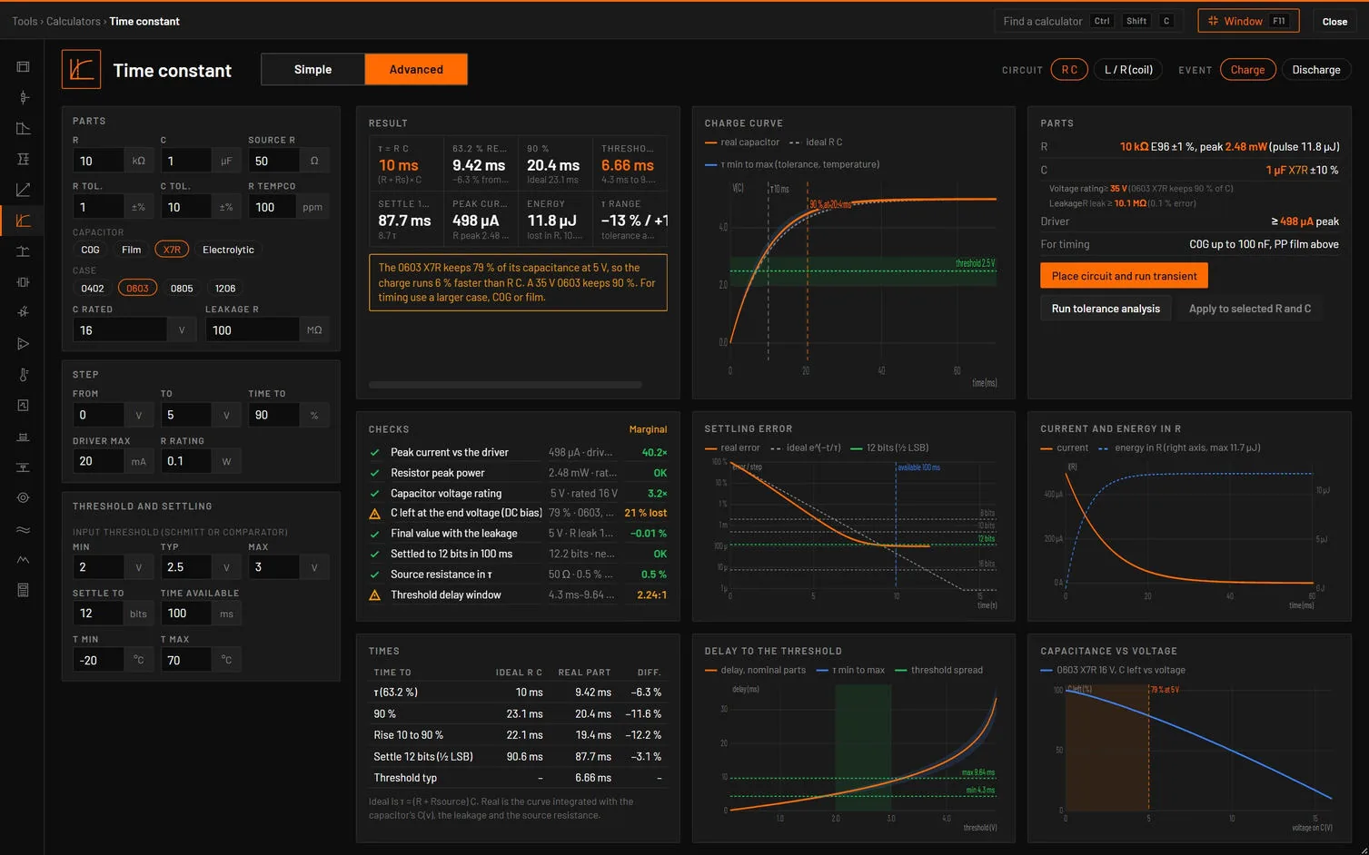
| Choice | Options | What it does |
|---|---|---|
| Circuit | R C, L / R (coil) | |
| Event | Charge, Discharge | R C. |
| Turn-off clamp | Diode, Diode + zener, Resistor | L / R: what takes the coil current when the switch opens. |
| Tab | Its dot | Cards |
|---|---|---|
| Step response | R C: amber with a warning. | Result, Charge curve (or Discharge curve), Times (coil: Coil current on and off, Clamps compared). |
| Settling and thresholds | The settling and threshold checks (coil: release and pick-up). | Settling error, Delay to the threshold, Checks (coil: Current after switch-off for each clamp, Coil current vs temperature). |
| Parts and stress | The stress checks. | Parts, Current and energy in R, Capacitance vs voltage (coil: Parts, Switch voltage at turn-off, Times). |
| Verify in simulation | None. | Calculator vs simulation. |
| Field | Unit | Default | What it does |
|---|---|---|---|
| R, C, Source R | kΩ, µF, Ω | 10, 1, 50 | Group Parts (R C). |
| R tol., C tol., R tempco | ±%, ±%, ppm | 1, 10, 100 | |
| Capacitor | C0G, Film, X7R, Electrolytic | X7R adds Case (0402, 0603, 0805, 1206) for its DC bias. C0G 0 ± 30 ppm/°C, PP film −200 ppm/°C, X7R ±15 % over temperature, electrolytic −20 / +10 %. | |
| C rated, Leakage R | V, MΩ | 16, 100 | |
| From, To, Time to | V, V, % | 0, 5, 90 | Group Step. |
| Driver max, R rating | mA, W | 20, 0.1 | |
| Threshold Min / Typ / Max | V | 2 / 2.5 / 3 | Group Threshold and settling: a Schmitt or comparator input. |
| Settle to, Time available | bits, ms | 12, 100 | |
| T min, T max | °C | −20, 70 | |
| Inductance, L tolerance, Coil resistance, Series R | mH, ±%, Ω, Ω | 500, 15, 400, 0 | Group Coil (L / R). |
| Supply, Diode drop, Zener, Clamp resistor | V, V, V, Ω | 12, 0.8, 24, 1000 | Group Drive and clamp. |
| Pick-up current, Release current, Release time max, Switch rating | %, %, ms, V | 75, 10, 5, 40 | Group Target. |
How it works it out. The RC step is integrated (fourth-order Runge-Kutta, 2400 steps over 12 τ) with the capacitor’s C(v), its leakage and the source resistance, against the ideal 1 − e−t/τ. An X7R keeps 1 − f (V/Vr)1.25 of its value (f is 0.95 for 0402, 0.9 for 0603, 0.8 for 0805, 0.65 for 1206), a smooth stand-in for vendor curves. Settling to N bits is |error| ≤ ½ LSB, ideally τ ln 2N+1. The energy lost in R is ½ C ΔV² for a linear C whatever R is. For a coil τ = L / (R + DCR), and at turn-off the clamp forces L di/dt = −(iR + Vc), so the switch sees the supply plus the clamp voltage. The τ range takes the corners of tolerance and temperature.
| Result | What it is |
|---|---|
| τ = R C | (R + source R) C. |
| 63.2 % real | When the real capacitor reaches 63.2 %, and how far from RC. |
| 90 % | Real, and ideal. |
| Threshold delay | At the typical threshold, and from the lowest threshold on the fastest curve to the highest on the slowest. |
| Settle 12 bits | Real time to ½ LSB, in τ. |
| Peak current, Energy, τ range | The current at t = 0 and its power in R, the energy lost and stored, the τ spread. |
| Coil: τ, Final current, Release time, Switch peak, Stored energy, Pick-up time, Coil hot, τ range | The coil current hot uses copper’s +0.393 %/°C. |
| Check | Value and limit | Passes | Marginal | Fails |
|---|---|---|---|---|
| Peak current vs the driver | I · driver max | 1.2 × margin | Within it | Over |
| Resistor peak power | I²R · rating | Within it | Over: read its pulse curve | |
| Capacitor voltage rating | V · rated | 1.5 × margin | Within it | Over |
| C left at the end voltage (DC bias) | X7R: % left | 90 % or more | 70 % or more | Less |
| Final value with the leakage | % short of the step | Under 0.1 % | Under 1 % | More |
| Settled to 12 bits in 100 ms | bits · time needed | All the bits | 85 % of them | Fewer: short |
| Source resistance in τ | % of R | Under 5 % | Under 12.5 % | More |
| Threshold delay window | min to max | Ratio 1.67:1 or less | Up to 2.86:1 | More |
| Switch voltage at turn-off (coil) | V · rating | 1.25 × margin | Within it | Over |
| Release time (coil) | time · the need | Within it | Up to 1.25 × it | Slow |
| Coil current hot vs pick-up | I hot · pick-up | 1.1 × margin | Equal | Less |
| Energy into the clamp, Inductance tolerance on τ | (information) |
| Message | When it shows |
|---|---|
| "The 0603 X7R keeps 79 % of its capacitance at 5 V, so the charge runs 6 % faster than R C. A 35 V 0603 keeps 90 %. For timing use a larger case, C0G or film." | An X7R losing more than 10 %. |
| "Peak current 133 mA at t = 0 is above the 20 mA driver limit, so the start of the curve is current-limited. Raise R to 1 kΩ or more." | Over the driver. |
| "11.7 bits in 100 ms. 12 bits need 108 ms (10.7 τ). Lower R or C, or lengthen the acquisition time." | Not settled in time. When the curve never settles within 12 τ the time reads –. |
| "R and the leakage resistance form a divider and the charge ends … % short of the step. Use a capacitor with a higher insulation resistance." | Leakage over 0.1 %. |
| "Electrolytics leak and drift with temperature and age. A time constant on one is ±20 % at best." | Electrolytic chosen. |
| "Diode clamp: switch at 12.8 V, release 2.32 ms. A slow release makes the contacts arc longer. A 24 V zener in series cuts the release to 434 µs with 36.8 V on the switch." | Coil with a diode clamp. |
| "At 70 °C the copper coil resistance is … % higher and the current drops to …, close to the pick-up current. Use a lower-voltage coil or a higher supply." | Coil hot near pick-up. |
| "Switch peak 42 V at turn-off is above the 40 V rating. Use a lower clamp voltage or a higher-rated transistor." | Over the switch rating. |
| Check | Analysis and measurement | Limit |
|---|---|---|
| Rise 10 to 90 % (Fall 90 to 10 %) | Transient of 12 τ with the real capacitor (cbias curve, rleak, tol) | ±3 % |
| Settling to 12 bits, Final value | Not measured | |
| Threshold crossing | Calculator only (the threshold spread is the receiving chip’s) | |
| Spread over tolerance | Tolerance analysis of the rise time | Inside the τ band |
| Switch peak at turn-off (coil) | Transient: max of V(SW) after the switch opens | ±3 % |
| Button | What it does |
|---|---|
| Place circuit and run transient | R C: a pulse source, RS, R1 and C1 with rleak and, for an X7R, its DC-bias curve cbias. Coil: the supply, L1 with dcr and dcr_tc, the clamp (D1, D1 and Z1, or RC1), a switch S1 driven to open at 6 τ, SW probed. |
| Run tolerance analysis | R C: tol on R and C, a Monte Carlo of 100 runs. Rise time against the tau band within the calculator’s band. |
| Apply to selected R and C (R and L) | Their values. |
| Simple | Advanced |
|---|---|
| Resistance, Capacitance, Inductance | R, C, Inductance |
| Circuit | Circuit |
| Time to reach | Time to |
- Open the time constant, press Advanced: 10 kΩ, 1 µF 0603 X7R 16 V, 50 Ω source, 0 to 5 V, a 2 to 3 V threshold, 12 bits in 100 ms.
You should seeRC is 10 ms, but the real capacitor reaches 63.2 % at 9.42 ms (−6.3 %) and 90 % at 20.4 ms against 23.1 ms ideal: the X7R keeps only 79 % of its capacitance at 5 V. The threshold is crossed at 6.66 ms, anywhere from 4.3 to 9.64 ms over the tolerances and threshold spread. 12 bits settle in 87.7 ms. Switch the capacitor to C0G and 12 bits need 108 ms: the check turns amber.
- Set Circuit to L / R (coil): 0.5 H, 400 Ω, 12 V, diode clamp.
- Compare the rows of Clamps compared.
You should seeτ 1.25 ms, 30 mA, pick-up at 75 % after 1.73 ms. The diode releases in 2.32 ms with 12.8 V on the switch. A 24 V zener releases in 434 µs at 36.8 V. A 1 kΩ resistor takes 822 µs but puts 42 V on a 40 V switch: that check fails.
Sources. First-order step response (any circuit theory text), TI’s Analog Engineer’s Pocket Reference for settling to N bits, and TE Connectivity’s note on relay coil suppression for the clamps. The tests check 63.2 %, ln 10, settling, the ½ CV² loss, an 0603 X7R at 5 V (79 %), the leakage divider, the coil turn-off against an independent integration, and the placed circuits against bspice.