
Crystal load capacitors
The two load capacitors of a Pierce crystal oscillator, as on a microcontroller’s XIN and XOUT pins: the values that make the crystal run at its marked frequency, the frequency error they give, and whether the oscillator has gain enough to start. The Advanced view adds the negative resistance, the drive level, the start-up time and the whole frequency budget for UART, USB, Ethernet, BLE or an RTC, with presets for a 16 MHz AT-cut crystal and a 32.768 kHz tuning fork. Group Parts. Search words include crystal, xtal, load capacitor, oscillator, pierce, ppm, cl and quartz.
The window, the Simple and Advanced views, full screen and the place buttons are in The calculator window.
59.1Simple: C1 = C2 for a CL
| Field | Unit | Default | What it does |
|---|---|---|---|
| Crystal load capacitance CL | pF | 18 | From the crystal datasheet. Reads a selected crystal’s cl. |
| Stray capacitance | pF | 3 | Pins, traces and the amplifier input. 2 to 5 pF is typical. |
| C1 = C2 | pF | 30 (solved) | The load capacitors, always the solved field. |
| Frequency | kHz, MHz | 16 MHz | Reads a selected crystal’s freq. |
| Tolerance | ppm | 20 | Plus and minus, with the stability if the datasheet adds it. |
| Shunt capacitance C0 | pF | 3 | |
| Motional capacitance C1 of the crystal | fF | 7 | |
| ESR | Ω | 40 | |
| Amplifier gm | µA/V, mA/V | 5 mA/V | From the MCU datasheet. The gain margin is gm over gm critical and must be 5 or more. |
C1 = C2 = 2 (CL − Cstray), from CL = C1 C2 / (C1 + C2) + Cstray. The tolerance in hertz is f × ppm / 10⁶. The pulling is Cm / (2 (C0 + CL)²) per pF, and the critical transconductance gmcrit = 4 ESR (2πf)² (C0 + CL)². With the nearest E12 capacitor, the frequency error is Cm/2 (1/(C0 + CL′) − 1/(C0 + CL)): a larger CL pulls the crystal below its marked frequency.
| Result | What it is |
|---|---|
| C1 = C2 | Exact (orange). |
| Nearest E12, CL with it, Error with it | The standard value, the CL it gives, and the frequency error in ppm. |
| Tolerance | ± Hz. |
| Pulling | ppm per pF. |
| gm critical, Gain margin, gm for margin 5 | The margin is gm / gmcrit. |
| Message | When it shows |
|---|---|
| "The standard E12 capacitor puts the crystal 11.1 ppm below its marked frequency. Use two capacitors in parallel or tune on the board." | Error over 10 ppm. |
| "The stray capacitance is as large as the load capacitance, so no positive capacitor gives the wanted CL. Check the crystal CL and the board stray value (2 to 5 pF is usual)." | C1 at or under 0. |
| "Load capacitors under about 5 pF are dominated by the pin and trace capacitance. Treat the result as a starting point and measure the stray capacitance." | C1 under 5 pF. |
| "Crystals with a CL under 6 pF are very sensitive to stray capacitance." | CL under 6 pF. |
| "The amplifier gm of 0.5 mA/V gives a gain margin of 1.5, below the 5 that AN2867 asks for. Use a crystal with a lower ESR or CL, or an amplifier with at least 1.64 mA/V." | Margin under 5. |
| "A CL above 32 pF is unusual and makes start-up harder because the amplifier needs more gain." | CL over 32 pF. |
The drawing shows the crystal with C1 and C2 to ground and the CL formula. There is no placed circuit: the oscillator’s amplifier (a gate or transistor, its bias and drive resistor) is your choice. Apply to the selected crystal and capacitors (or Apply to the selected load capacitors) writes the nearest E12 value into each selected capacitor and CL into a selected crystal.
- Open the crystal calculator (type
crystal): CL 18 pF, 3 pF stray, 16 MHz, ESR 40 Ω, gm 5 mA/V.
You should seeC1 = C2 = 30 pF. The nearest E12 is 33 pF, which gives CL 19.5 pF and −11.1 ppm, so the amber warning suggests two capacitors in parallel. ±20 ppm is ±320 Hz, the pulling 7.94 ppm/pF, gmcrit 0.713 mA/V and the gain margin 7.0 ×.
59.2Advanced: margin, drive and budget
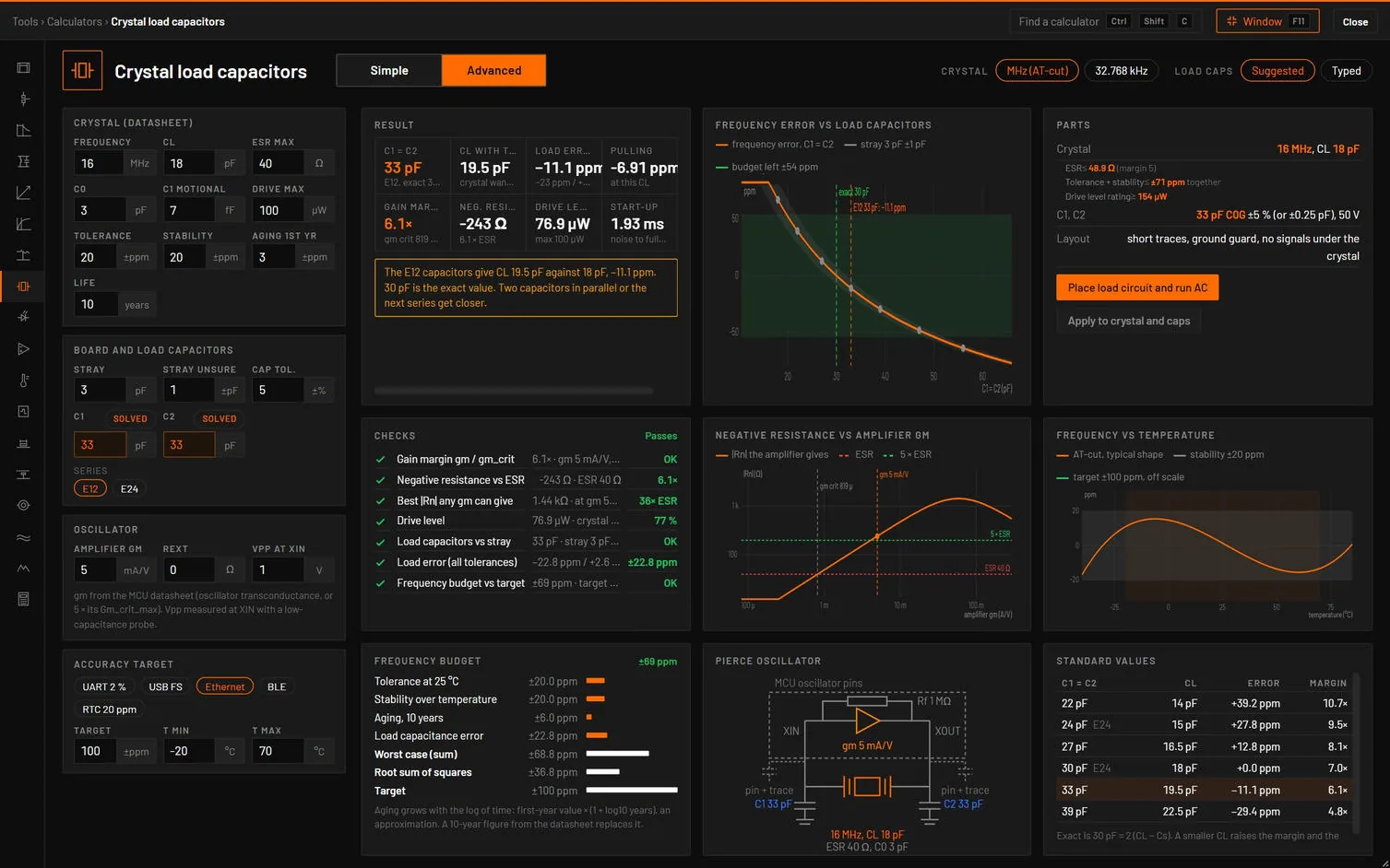
| Choice | Options | What it does |
|---|---|---|
| Crystal | MHz (AT-cut), 32.768 kHz | Loads a preset: 16 MHz, CL 18 pF, ESR 40 Ω, or a tuning fork with CL 12.5 pF, ESR 50 kΩ, C0 1.2 pF, 2.5 fF, 1 µW, gm 10 µA/V, an RTC target of 20 ppm. |
| Load caps | Suggested, Typed | Suggested: the nearest value of the series to 2 (CL − Cs), SOLVED. |
| Tab | Its dot | Cards |
|---|---|---|
| Load capacitors | The load and stray checks. | Result, Frequency error vs load capacitors, Standard values. |
| Oscillator margin and drive | The margin, negative resistance and drive checks. | Negative resistance vs amplifier gm, Pierce oscillator, Checks. |
| Frequency budget | The budget check. | Frequency budget, Frequency vs temperature, Parts. |
| Verify in simulation | None. | Calculator vs simulation. |
| Field | Unit | Default | What it does |
|---|---|---|---|
| Frequency, CL, ESR max, C0, C1 motional, Drive max | MHz, pF, Ω, pF, fF, µW | from the preset | Group Crystal (datasheet). |
| Tolerance, Stability, Aging 1st yr, Life | ±ppm, ±ppm, ±ppm, years | 20, 20, 3, 10 | The fork has no stability figure: its temperature parabola is used. |
| Stray, Stray unsure, Cap tol. | pF, ±pF, ±% | 3, 1, 5 | Group Board and load capacitors. |
| C1, C2, Series | pF | SOLVED, E12 or E24 | |
| Amplifier gm, Rext, Vpp at XIN | mA/V, Ω, V | 5, 0, 1 | Group Oscillator. gm from the MCU datasheet (or 5 × its Gm_crit_max). Vpp measured at XIN with a low-capacitance probe. |
| Accuracy target | UART 2 %, USB FS, Ethernet, BLE, RTC 20 ppm | Sets the target: 20 000, 2500, 100, 50 or 20 ppm. | |
| T min, T max | °C | −20, 70 |
How it works it out. f(CL) = fs (1 + Cm / (2 (C0 + CL))), the relation of the engine’s crystal part. gmcrit = 4 (ESR + Rext) (2πf)² (C0 + CL)², margin ≥ 5 (ST AN2867). The negative resistance follows Vittoz, Degrauwe and Bitz (IEEE JSSC 1988) with C0 and the pin capacitance, and equals AN2867 at small gm. The start-up time is the growth from noise to full amplitude at the net negative resistance. The drive is I = 2πf Vpp Ctot / 2√2 at XIN and DL = ESR I² (AN2867). The budget adds tolerance, stability (for the fork its parabola, −0.034 ppm/K² typical), aging × (1 + log10 years), and the worst load error over the capacitor and stray tolerances.
| Result | What it is |
|---|---|
| C1 = C2 | The series value and the exact one. |
| CL with them | Against what the crystal wants. |
| Load error | ppm, and its range with the tolerances. |
| Pulling | ppm/pF, negative: a larger CL lowers f. |
| Gain margin | With gmcrit. Amber under 5. |
| Neg. resistance | In multiples of the ESR. |
| Drive level | Against the maximum. Red over it. |
| Start-up | Noise to full amplitude, an estimate, or never. |
The Parts card gives the ESR the crystal may have for a margin of 5, the tolerance and stability it may have for the target (or no crystal fits: TCXO), the drive rating, C1 and C2 (C0G), Rext when the drive is too high, and the layout (short traces, ground guard, no signals under the crystal). Standard values lists the series values around the exact one with their CL, error and margin.
| Check | Value and limit | Passes | Marginal | Fails |
|---|---|---|---|---|
| Gain margin gm / gm_crit | margin | 5 or more | 3 or more | Less: low |
| Negative resistance vs ESR | |Rn| · ESR + Rext | 5 × or more | 3 × or more | Less |
| Best |Rn| any gm can give | the peak · ESR | 5 × or more | 3 × or more | Less |
| Drive level | DL · crystal max | 1.25 × margin | Within it | Over |
| Load capacitors vs stray | smaller of C1, C2 | 6 pF or more | Less: the stray rules | |
| Load error (all tolerances) | ppm | Under a quarter of the target | Under half | More |
| Frequency budget vs target | ± ppm · target | Within it | Up to 1.25 × it | Over |
| Message | When it shows |
|---|---|
| "Gain margin 1.4 is below 5, so start-up over temperature and aging is uncertain. Use a crystal with ESR ≤ 40.9 Ω or a lower CL (4 pF gives margin 5), or a stronger drive setting." | Margin under 5. |
| "Drive level 437 µW is over the crystal’s 50 µW. It ages fast and can crack. Add Rext ≈ 995 Ω (the reactance of C2, AN2867), which gives a margin of 0.2, or lower the drive setting." | Over the drive limit. |
| "Worst-case budget ±138 ppm against the ±20 ppm target (the 32.768 kHz tuning fork loses up to 100 ppm at the temperature ends). 8.6 s/day. Calibrate in firmware or use a TCXO or a compensated RTC." | Over the target (an AT-cut crystal: use ±10 ppm / ±10 ppm or a TCXO). |
| "The E12 capacitors give CL 19.5 pF against 18 pF, −11.1 ppm. 30 pF is the exact value. Two capacitors in parallel or the next series get closer." | Load error over 5 ppm. |
| "gm_crit passes but the negative resistance with C0 and the pin capacitance is below 3 × ESR. Use a smaller CL." | The fuller model disagrees. |
| Check | Analysis and measurement | Limit |
|---|---|---|
| Load error (loop resonance) | AC around the loaded frequency: the loop phase of the crystal with C1 and C2 (each with 2 Cs) and the AC source in the loop | ±6° at the calculated frequency |
| Negative resistance, Start-up, Frequency spread | Calculator only |
| Button | What it does |
|---|---|
| Place load circuit and run AC | V1 at the loaded frequency, X1 (freq, cl, esr, c0, cm), C1 and C2 with the stray, a 1 Ω sense resistor and 1 GΩ DC paths, IN and OUT, an AC sweep of ±300 ppm. Loop phase at the loaded frequency within ±6°. The amplifier, start-up and drive are not simulated. |
| Apply to crystal and caps | C1 into the selected capacitors, CL into a selected crystal. |
| Simple | Advanced |
|---|---|
| CL, Stray capacitance, Frequency, ESR, C0, motional C1, Amplifier gm, Tolerance | The same fields of the Crystal, Board and Oscillator groups |
- Open the crystal calculator and press Advanced (16 MHz preset, E12, Ethernet ±100 ppm).
- Look at Frequency budget, then set Crystal to 32.768 kHz.
You should see33 pF gives CL 19.5 pF: −11.1 ppm (−23 to +3 ppm with the tolerances), margin 6.1 ×, |Rn| 243 Ω, drive 76.9 µW of 100 µW, start-up 1.93 ms. The budget is ±68.8 ppm (tolerance 20, stability 20, aging 6.0, load 22.8) against ±100: all checks pass. The tuning fork gets 22 pF, but its temperature parabola makes the budget ±138 ppm against the 20 ppm RTC target, 8.6 s/day: the budget check fails.
Sources. ST AN2867, NXP and Abracon application notes, Epson for the tuning fork, and Vittoz, Degrauwe and Bitz, IEEE JSSC 23(3) 1988. The tests check gmcrit 713.1 µA/V for 16 MHz, 40 Ω, 3 pF and 18 pF, the exact load error (33 pF: −11.1 ppm), the Vittoz curve, the fork’s parabola and 0.0864 s/day per ppm, Rext, and the placed load circuit’s zero loop phase.