A copper wire or cable: its resistance and drop, the current it carries in air before its insulation is too hot, and the current and time that melt it. The Advanced view adds stranded wire, bundles, a round trip, the skin effect, a fault with its clearing time and the fuse that protects the wire, the smallest size that works, and inserts the wire into your circuit. Group PCB. Search words include wire, awg, gauge, mm2, ampacity, fusing, onderdonk, preece and cable.
The window, the Simple and Advanced views, full screen and the place buttons are in The calculator window.
64.1Simple: size, drop and fusing
Simple: size, drop and fusing
Choice
Options
What it does
Size in
AWG, mm²
Solid wire.
Insulation
PVC 70 °C, PVC 105 °C, XLPE 125 °C, Silicone 180 °C, PTFE 200 °C
The temperature the ampacity is taken at.
Conductor
Solid, Stranded
Simple: size, drop and fusing
Field
Unit
Default
What it does
AWG (0000 = −3, 000 = −2, 00 = −1)
22
Solid, AWG.
Cross section
mm²
0.5
Solid, mm².
Strands, AWG of one strand
7, 30
Stranded.
Length
m, ft, cm, mm
1 m
Wire temperature
°C
20
For the resistance.
Operating current
A, mA
0.5 A
Reads the measured RMS current of a selected wire or part.
Fault current
A
100
SOLVE.
Time to fuse
s, ms
0.1 s (solved)
SOLVE, solved when the calculator opens.
Ambient, Insulation wall
°C, mm
25, 0.4
The AWG diameter is 0.127 mm × 92(36 − n)/39 (ASTM B258). Stranded wire is the strands’ area, with 2 % more resistance for the lay. ρ = 1.7241 × 10⁻⁸ Ω m at 20 °C, +0.393 %/K. The ampacity is a heat balance of the insulated wire in still air (Churchill and Chu convection, radiation, the wall as a thermal resistance) at the insulation’s rating, within 8 % of NEC Table 310.17 for a single conductor in free air. Fusing: Onderdonk, I = A √(log10(1 + (1083 − Ta)/(234 + Ta)) / 33t) with A in circular mils, and Preece’s steady melting current I = 10244 d1.5 (d in inches).
Simple: size, drop and fusing
Result
What it is
R per length
Ω/km (orange).
Total resistance, Voltage drop, Power loss, Cross section
Ampacity, Conductor temp
The current at the insulation rating, and the conductor’s temperature at the operating current.
Fusing current, Fusing time
Orange for the solved one.
Melting current (Preece)
Simple: size, drop and fusing
Message
When it shows
"10 A is above the ampacity of 3.19 A for PVC 105 °C at 60 °C. Use a larger size or a higher insulation class."
"Under 5 ms the heating is not adiabatic for thick wire and Onderdonk is optimistic at the short end. Check the fuse maker curves."
"Onderdonk assumes no heat leaves the wire, which fails for long times. Beyond about 10 s use Preece, the steady melting current."
"The size is outside the AWG 0000 to 40 range."
"Above 105 °C most insulation is past its rating."
Wire temperature over 105 °C.
"The fault current is below the operating current."
The plot Fusing current against time (Onderdonk) runs from 1 ms to 10 s, and the table Neighbouring sizes gives three sizes each way. Add the wire as a resistor in series and run (with a straight wire of 4 grid units selected) puts R_WIRE into it, with no measurements.
Try it
22 AWG
Open Wire gauge and fusing (type awg): 22 AWG solid, PVC 105 °C, 1 m, 0.5 A, 100 A fault.
Press SOLVE on Fault current with Time to fuse 0.1 s.
You should see52.96 Ω/km, 53 mΩ, 26.5 mV, 0.3255 mm², ampacity 12.1 A, 25.2 °C. 100 A melts it in 883 ms, 297 A in 0.1 s, and Preece’s steady melting current is 41.3 A.
64.2Advanced: cables, faults and fuses
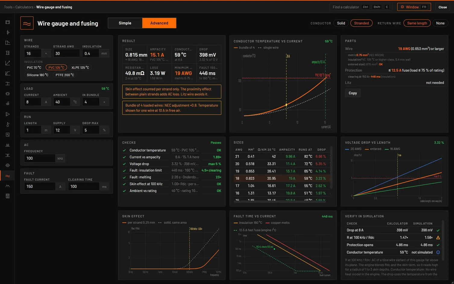
Figure 64.1Wire gauge and fusing, Advanced, in full screen: a 16 × 30 AWG stranded wire at 8 A in a bundle of four, with the parts, the checks, the conductor temperature against current, the sizes, the drop against length, the skin effect and the fault times.
Advanced: cables, faults and fuses
Choice
Options
What it does
Conductor
Solid, Stranded
Size in
AWG, mm²
Solid.
Return wire
Same length, None
Same length counts the run there and back.
Advanced: cables, faults and fuses
Tab
Its dot
Cards
Design
Temperature, ampacity, drop.
Result, Parts, Checks.
Ampacity
Temperature, ampacity, ambient.
Conductor temperature vs current, Sizes.
Voltage drop
Drop.
Voltage drop vs length, Sizes.
Skin effect
Skin effect.
Skin effect, Skin depth.
Faults
Insulation limit and melting.
Fault time vs current, Fault checks.
Verify in simulation
None.
Calculator vs simulation.
Advanced: cables, faults and fuses
Field
Unit
Default
What it does
Strands, Strand AWG (or AWG, Section)
16, 30 (18, 1.0 mm²)
Group Wire.
Insulation (wall), Emissivity
mm
0.4, 0.9
Insulation
PVC 70 °C, PVC 105 °C, XLPE 125 °C, Silicone 180 °C, PTFE 200 °C
Current, Ambient, In bundle
A, °C, ×
8, 40, 4
Group Load, badge the conductor temperature.
Length, Supply, Drop max
m, V, %
1, 12, 5
Group Run.
Frequency
kHz
100
Group AC.
Fault current, Clearing time
A, ms
150, 100
Group Fault.
How it works it out. The heat balance I²R′(Tc) = (Tc − Ts)/R′ins = hπD(Ts − Ta), with h from Churchill-Chu convection and radiation. A bundle derates the ampacity by the NEC 310.15(C)(1) factors (0.8 for 4 to 6 wires, 0.7 for 7 to 9, 0.5 for 10 to 20 and so on). The skin effect is the exact Bessel solution for a round wire, per strand for stranded wire. A fault uses IEC 60949, I²t = k²S², to the insulation’s short-circuit limit (160 °C for PVC, 250 °C for XLPE, 350 °C for silicone, 300 °C for PTFE), and to 1083 °C for melting. The fuse suggested is the first standard rating at or above the load / 0.75, and a fast fuse opens in 0.7 × rated² / fault² (the engine’s fuse). The minimum size is the smallest AWG and IEC 60228 size that meet the ampacity and the drop.
Advanced: cables, faults and fuses
Result
What it is
Size
mm² and its AWG.
Ampacity
With the bundle factor (orange).
Conductor
Its temperature. Red over the rating.
Drop, Resistance, Loss
Red over the drop limit.
Minimum size
AWG and metric (orange).
Fault 150 A
The time to the insulation limit, and when it melts.
Advanced: cables, faults and fuses
Check
Value and limit
Passes
Marginal
Fails
Conductor temperature
Tc · rating, bundle
10 % room
Within it
Too hot
Current vs ampacity
ampacity / I
1.25 × or more
1 × or more
Less
Voltage drop
% · max
Within it
Up to 1.18 × it
More
Fault: insulation limit
time · clearing
2 × or more
1 × or more
Less
Fault: melting
time · clearing
5 × or more
1 × or more
Less
Skin effect at 100 kHz
Rac/Rdc
1.2 or less
More: use litz
Ambient vs rating
rating − Ta · 20 °C
20 °C room or more
10 °C or more
Less
Advanced: cables, faults and fuses
Message
When it shows
"Conductor at 161 °C at 6 A, rating 105 °C (PVC 105 °C, bundle ×0.8). Use 13 AWG or a higher insulation class."
Too hot.
"Drop 103.98 % over 10 m of wire, limit 5 %. 13 AWG (2.62 mm²) or 2.5 mm² meets it."
Over the drop.
"At 300 A the insulation reaches its 160 °C limit after 0 s, before the 500 ms clearing time. A 8 A fast fuse opens in about 498 µs."
The fault damages the insulation.
"Skin depth 29.6 µm at 5 MHz: Rac is 3.69× Rdc. Use litz with strands under 59.1 µm."
Rac over 1.2 × Rdc.
"Skin effect counted per strand only. The proximity effect between plain strands adds AC loss. Litz wire avoids it."
Stranded.
"Bundle of 4 loaded wires: NEC adjustment ×0.8. Temperature shown for one wire at 10 A in free air."
More than 3 in the bundle.
The Parts card gives the wire (AWG and IEC 60228), the insulation and wall, whether the entered size is enough, the fuse and its clearing time, and litz when needed, with Copy.
Advanced: cables, faults and fuses
Check
Analysis and measurement
Limit
Drop at 8 A
Operating point of R_WIRE at the conductor temperature
Equal
R at 100 kHz / Rdc
AC of a wire transmission line of this gauge far above its plane. The engine blends Rdc and the skin term, so it reads high at 1 to 3 skin depths
Within 5 %
Protection opens
The fuse’s opening time
Before the insulation limit
Conductor temperature
Not simulated
Advanced: cables, faults and fuses
Button
What it does
Insert in wire and run
R_WIRE, the whole run (both ways with a return wire). See below.
Place fault test
A 12 V source, the suggested fast fuse F1 and a resistor that sets the fault current, a transient past the fuse’s opening. Fault current, Fuse still closed, Fuse open and Open before the insulation limit.
Insert in wire and run puts the wire into your circuit: select a straight wire first (horizontal or vertical, at least 4 grid units long, 8 for the via’s two parts). The part goes in series at the middle of the wire, 4 grid units long, and the wire is split at its pins. It is a resistor R_WIRE with copper’s tempco (tc1 0.00393, tnom 20 °C) at the worst-corner temperature, so it has the calculator’s hot resistance. Then the live view runs, an operating point is taken, and two measurements are added: current against the calculator (PASS up to the design current) and drop, % of the calculator’s (PASS up to 100.1 %). A wire that carries more than the design current fails both. It is one undo step, and a name in use becomes R_WIRE2. The button’s tooltip asks for a wire at least 8 grid units long in all three, while the trace and wire need only 4.
Open Wire gauge and fusing and press Advanced: 16 × 30 AWG, PVC 105 °C, 8 A at 40 °C in a bundle of four, 1 m there and back on 12 V, a 150 A fault cleared in 100 ms.
Press Place fault test.
You should see0.815 mm² (about 18 AWG), ampacity 15.1 A (18.9 A alone × 0.8), 58.9 °C, 49.8 mΩ over 2 m, 398 mV (3.32 %). 19 AWG or 0.75 mm² would do. A 12.5 A fast fuse opens the 150 A fault in 4.86 ms, long before the insulation reaches 160 °C (446 ms). All checks pass, and the fault test passes its four measurements.
Sources. ASTM B258 (AWG, copper), NEC Table 310.17 and 310.15(C)(1), IEC 60228 sizes, IEC 60949 (adiabatic short circuit), Onderdonk and Preece (fusing), Churchill and Chu (convection), the exact skin effect of a round wire. The tests check NEC 310.17 within 8 % for 12, 14 and 10 AWG, the bundle factors, k, Preece, the skin effect, the round-trip drop, the smallest size, R_WIRE, and the fuse opening time against bspice.