
Trace current and width
How wide a copper trace must be for a current and a temperature rise, and what it then drops and dissipates. The Simple view uses IPC-2221 or IPC-2152. The Advanced view sizes the trace on its worst manufacturing corner (IPC-6012 minimum copper, etched narrow) with the IPC-2152 modifiers for the board, a plane and the laminate, adds the AC ripple’s skin loss, a fault pulse and the fusing time, and can insert the trace into a wire of your circuit. Group PCB. Search words include trace, track, width, current, ipc-2221, ipc-2152, copper and ampacity.
The window, the Simple and Advanced views, full screen and the place buttons are in The calculator window.
61.1Simple: width for a current
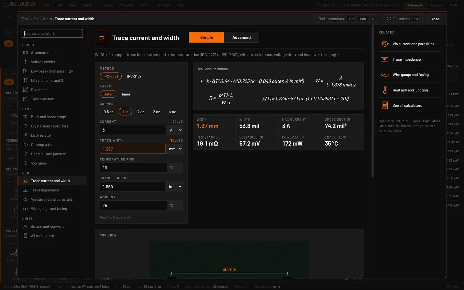
| Choice | Options | What it does |
|---|---|---|
| Method | IPC-2221, IPC-2152 | |
| Layer | Outer, Inner | |
| Copper | 0.5 oz, 1 oz, 2 oz, 3 oz, 4 oz | 1 oz = 1.378 mil = 35 µm. |
| Copper plane next to the trace | No plane, Plane under it | IPC-2152. |
| Field | Unit | Default | What it does |
|---|---|---|---|
| Current | A, mA | 3 A | SOLVE. Reads the measured RMS current of a selected wire or two-pin part while the live view runs. |
| Trace width | mm, mil, µm | 1.5 mm (solved) | SOLVE, solved when the calculator opens. |
| Temperature rise | °C | 10 | 1 to 150. |
| Trace length | mm, in, mil, cm | 50 mm | |
| Ambient | °C | 25 | |
| Board thickness | mm, mil | 1.6 mm | IPC-2152. Thin boards run hotter. Chart range 0.72 to 2.36 mm. |
| Distance to the plane | mm, mil | 0.2 mm | IPC-2152 with a plane. Chart range 0.14 to 2.4 mm. |
IPC-2221: I = k ΔT0.44 A0.725 with A in mil² and k = 0.048 outer, 0.024 inner, and the width A / t. IPC-2152 uses the Brooks and Adam fit of its charts (ΔT = K Ia Wb Thc, per layer and copper weight) and the modifiers for the board thickness and a plane. R = ρ(T) L / (W t) with ρ = 1.724 × 10⁻⁸ Ω m and +0.393 %/K at the trace temperature.
| Result | What it is |
|---|---|
| Width (mm), Width (mil) | Orange when solved. |
| Max current | Orange when solved. |
| Cross section | mil². |
| Resistance, Voltage drop, Power loss, Trace temp | At ambient + rise. |
Drawings: the trace from above with its length and width (it glows hotter with the rise), the cross section, and a table Width for 3 A and +10 °C, by copper for outer and inner layers.
| Message | When it shows |
|---|---|
| "IPC-2221 charts stop at 35 A. Above that the formula is an extrapolation, check with a thermal model." | Over 35 A. Also over 400 mil wide, a rise outside 10 to 100 °C, or a section outside 1 to 250 mil². |
| "The IPC-2152 data covers 1 to about 100 °C of rise." | Also: the fit is documented for 5 to 400 mil, the data goes up to about 25 A. |
| "Estimate: the board thickness and the plane distance change the rise by factors fitted to the IPC-2152 modifier charts by a third party. They agree with the Brooks and Adam plane simulation within about 10 %. Check a tight design with a thermal model." | IPC-2152 with a plane or another board thickness. |
| "The trace runs at 145 °C. FR-4 glass transition is about 130 to 170 °C, keep margin and mind nearby parts." | Over 105 °C. |
| "A trace under 3 mil is limited by the fabricator, not by the current." |
| Button | What it does |
|---|---|
| Add the trace to the circuit and run | With a straight wire selected: R_TRACE (the Simple resistance, no tempco) in series with it, in the live view. No measurements. |
| Note on the trace’s wire | A text above the selected wire: PCB trace 1.37 mm (53.8 mil) x 50 mm, 1 oz outer, 19.1 mΩ, 3 A for +10 °C. |
- Open Trace current and width (type
trace): IPC-2221, outer, 1 oz, 3 A, +10 °C, 50 mm. - Set Method to IPC-2152 and Plane under it.
You should seeIPC-2221: 1.37 mm (53.8 mil), 74.2 mil², 19.1 mΩ, 57.2 mV, 172 mW at 35 °C. With IPC-2152 and a plane 0.2 mm under it the same current needs a much narrower trace: a plane lets a trace carry about twice the current for the same rise.
61.2Advanced: the worst corner
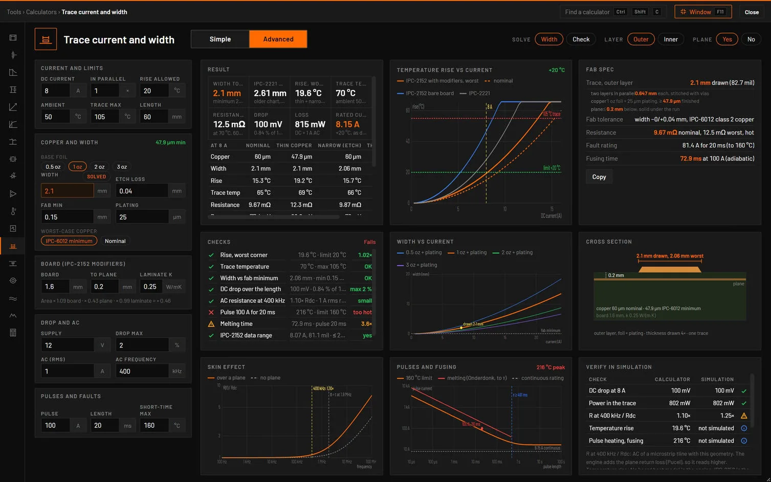
| Choice | Options | What it does |
|---|---|---|
| Solve | Width, Check | Width works out the width to draw (SOLVED). Check takes a typed width. |
| Layer | Outer, Inner | |
| Plane | Yes, No |
| Tab | Its dot | Cards |
|---|---|---|
| Design | Rise, trace temperature, width against the fab minimum. | Result, Fab spec, Cross section, Corners. |
| Heat | Rise and trace temperature. | Temperature rise vs current, Checks, Width vs current, Methods, worst corner. |
| Drop and AC | DC drop and AC resistance. | Skin effect, Drop and loss, Drop vs current. |
| Pulses | Pulse and melting time. | Pulse current vs length, Pulse checks. |
| Verify in simulation | None. | Calculator vs simulation. |
| Field | Unit | Default | What it does |
|---|---|---|---|
| DC current, In parallel | A, × | 8, 1 | Group Current and limits. |
| Rise allowed, Ambient, Trace max, Length | °C, °C, °C, mm | 20, 50, 105, 60 | |
| Base foil | 0.5, 1, 2, 3 oz | Group Copper and width, badge the minimum copper. | |
| Width | mm | SOLVED (2.5 typed) | |
| Etch loss, Fab min, Plating | mm, mm, µm | 0.04, 0.15, 25 | Plating on an outer layer. |
| Worst-case copper | IPC-6012 minimum, Nominal | IPC-6012 minimum after processing: outer 33.4, 47.9, 78.7, 108.0 µm, inner 11.4, 24.9, 55.9, 86.9 µm for 0.5 to 3 oz. | |
| Board, To plane, Laminate k | mm, mm, W/mK | 1.6, 0.2, 0.25 | Group Board (IPC-2152 modifiers), badge clamped outside the chart ranges, and the area multiplier line. |
| Supply, Drop max, AC (rms), AC frequency | V, %, A, kHz | 12, 2, 1, 400 | Group Drop and AC. |
| Pulse, Length, Short-time max | A, ms, °C | 100, 20, 160 | Group Pulses and faults. |
How it works it out. IPC-2152 with the modifiers for board, plane and laminate (each held at its chart end). Four corners: Nominal, Thin copper, Narrow (etch), Thin + narrow. The width is sized on the worst one, and the width to draw is that plus the etch loss, rounded up to 0.05 mm and at least the fab minimum. The current per trace is the DC current over the traces in parallel, and the AC ripple heats as √(Idc² + Iac² R(f)/Rdc), with R(f) from the skin form of the engine’s transmission line. A pulse uses a one-pole thermal model (copper’s 3.45 MJ/m³K, the time constant a lower bound), and the melting time the adiabatic IEC 60949 formula with Onderdonk’s 1083 °C.
| Result | What it is |
|---|---|
| Width to draw (Width needed in Check mode) | Orange. Red in Check mode when the need is wider than drawn. |
| IPC-2221 width | The older chart, for comparison. |
| Rise, worst, Trace temp | Red over the allowed rise. |
| Resistance, Drop, Loss | At the worst temperature, the drop as % of the supply, DC plus AC loss. |
| Rated current | What the drawn trace carries on its worst corner for the allowed rise (orange). |
The Corners table gives copper, width, rise, temperature, resistance, drop and loss for each corner, the worst in orange. The Fab spec gives the width in mm and mil (and on two stitched layers), the copper to require, the plane, the tolerance, the resistance, the fault rating and the fusing time, with Copy. Methods, worst corner compares IPC-2152 with modifiers, IPC-2152 bare board and IPC-2221.
| Check | Value and limit | Passes | Marginal | Fails |
|---|---|---|---|---|
| Rise, worst corner | rise · allowed | Within it | Up to 1.11 × it | More |
| Trace temperature | T · trace max | 10 % room | Within it | Over: hot |
| Width vs fab minimum | width · minimum | At or over | Under | |
| DC drop over the length | % of supply · max | Within it | Up to 1.25 × it | More |
| AC resistance at 400 kHz | × Rdc | 1.5 × or less: small | More: skin loss | |
| Pulse 100 A for 20 ms | peak T · short-time max | Within it | Up to 1.11 × its rise | More: too hot |
| Melting time | time · pulse length | 10 × or more | 2 × or more | Less |
| IPC-2152 data range | I, width, rise | Inside | Outside: extrapolated | |
| Modifier range | board, plane, laminate | All inside | Clamped |
| Message | When it shows |
|---|---|
| "Worst corner (thin + narrow): rise 769 °C, limit 10 °C. Draw at least 41.9 mm, or 12.6 mm on each of two layers." | Too narrow (Check mode). |
| "Trace at 854 °C, limit 105 °C. Lower the allowed rise or the ambient." | Over the trace maximum. |
| "100 A for 20 ms heats the trace to 216 °C, limit 160 °C. Draw at least 2.65 mm or clear the fault sooner." | The pulse is too hot. |
| "The trace melts after 229 µs at 300 A. Clear the fault well before that." | Melting under 2 × the pulse. |
| "No plane under the trace. A plane 0.2 mm below lowers the IPC-2152 rise by 2.6×." | Plane No. |
| "2 traces in parallel are treated as thermally separate. Side by side on one layer they heat each other (IPC-2152 section 5)." | More than one. |
| "Board thickness outside the chart range of 0.72 to 2.36 mm. Modifier held at the chart end value." | Also for the plane distance and the laminate. |
| Check | Analysis and measurement | Limit |
|---|---|---|
| DC drop at 8 A, Power in the trace | Operating point of R_TRACE at the trace temperature | Equal |
| R at 400 kHz / Rdc | AC of a microstrip transmission line of this geometry. The engine adds the plane’s return loss (Pucel), so it reads higher | Within 10 % |
| Temperature rise, Pulse heating, fusing | Not simulated: the engine has no board heat model. A fuse part in series shows when the protection opens |
| Button | What it does |
|---|---|
| Insert in wire and run | See below. |
| Place line and run AC | A source at the ripple frequency, RS = Z0, a microstrip tline with the worst-corner width, copper, height and length, a matched load, and an AC sweep. Trace loss at 400 kHz between the calculator’s and the engine’s copper loss. |
Insert in wire and run puts the trace into your circuit: select a straight wire first (horizontal or vertical, at least 4 grid units long, 8 for the via’s two parts). The part goes in series at the middle of the wire, 4 grid units long, and the wire is split at its pins. It is a resistor R_TRACE with copper’s tempco (tc1 0.00393, tnom 20 °C) at the worst-corner temperature, so it has the calculator’s hot resistance. Then the live view runs, an operating point is taken, and two measurements are added: current against the calculator (PASS up to the design current) and drop, % of the calculator’s (PASS up to 100.1 %). A wire that carries more than the design current fails both. It is one undo step, and a name in use becomes R_TRACE2. The button’s tooltip asks for a wire at least 8 grid units long in all three, while the trace and wire need only 4.
| Simple | Advanced |
|---|---|
| Current, Trace width, Temperature rise, Trace length, Ambient, Board thickness | DC current, Width, Rise allowed, Length, Ambient, Board |
| Layer, Copper (4 oz → 3 oz), Plane | Layer, Base foil, Plane |
- Open Trace current and width, press Advanced: 8 A, +20 °C over 50 °C, 1 oz outer with 25 µm plating, a plane 0.2 mm under it, 60 mm.
- Open Pulses.
You should seeDraw 2.1 mm (2.065 mm needed on the thin + narrow corner, 47.9 µm copper, area × 0.46 from the board, plane and laminate). IPC-2221 would ask 2.607 mm, IPC-2152 bare board 4.40 mm. Worst corner: 19.6 °C rise, 69.6 °C, 12.53 mΩ, 100 mV (0.84 %), 0.815 W, rated 8.15 A. The 100 A, 20 ms fault heats it to 216 °C against 160 °C: Pulse fails, and the warning asks for 2.65 mm. It would melt after 72.9 ms (3.6 ×, amber).
Sources. IPC-2221 (section 6.2, chart 6-4), IPC-2152 (2009) with the Brooks and Adam fit (“Trace Currents and Temperatures Revisited”, 2015) and the section 5 modifiers as fitted by NinjaCalc, IPC-6012 for the minimum copper, IEC 60949 and Onderdonk for fusing. The tests check IPC-2221 at 1 A and 3 A (11.8 and 53.8 mil), the plane and board factors, 1 oz 10 mil 1 inch at 49 mΩ, the pulse model against the adiabatic form, Onderdonk’s 14.7 A for 30 AWG in 1 s, and the placed R_TRACE and line against bspice.